Testing to Find the Fastest Bicycle Wheels
Precursor – The critics and those with a vested interest
I have added this section to the start of this blog post. The method this test uses is called transient state and it is used when aerodynamics are constantly changing. This is difficult to explain in detail in one blog post so I have linked to a youtube video.
The important part of the video is at 10m20 and this shows the difference between airflow that exists in the real world, airflow that manufacturers test at and a (turbulent) transient test. The flow that is generated in a steady state wind tunnel rarely occurs in real life and is borderline acceptable for a velodrome.
Be aware that a lot of wheel companies use internet forum users as a method of subversively selling a reality that does not exist under a premise of an impossible power saving. I DO NOT SELL WHEELS SO I HAVE NO VESTED INTERESTS and remain impartial.
In short, the wheel companies are exaggerating their power savings and testing using methods THAT ARE INAPPROPRIATE FOR ROAD USE. They test at speeds that most 95% of the population cannot achieve and use conditions that do not take into account the random nature of the environment.
Introduction
In terms of drag caused by a bicycle rider, the biggest loss is caused by the rider themselves followed by the wheels and frame.
The drag caused by wheels is significant because of two fundamental reasons. The first is they hit the air first as they are the most forward part of the bike and second because they are rotating. The effective air speed at the top of a wheel/tyre is double the indicated speed of the bike.
In the bike industry, wheel aerodynamic testing has generally been conducted by two groups of people – Wheel manufacturers and journalists. Wheel manufacturers will usually adjust tests to make their particular wheels look more favourable than their competitors in testing. This is usually achieved by a combination of adjusting speeds and angles. The reality is this type of test is not impartial.
Journalists on the other hand tend to visit their local university and ask some clever boffin to conduct their testing for them and give them the results or go to their local velodrome, hold a speed and see how much power the wheels consume.
Both of the above testing methodologies are not representative of the real world. A comparative analogy would be fuel consumption for a car driving along a perfectly smooth glass like road surface with no wind and no change in speed – it is totally unrealistic.
The testing that has been carried out is usually steady state. A steady state analysis assumes the wheels, bike and rider are in a nice environment where air is hitting them at a perfect speed and perfect angle. The drag is then recorded.
In the real world, very few riders have the ability to maintain a speed of 50km/h for a length of time as they are simply not fit enough. The reality is on the open road, wind does not come in from a perfect angle, it’s speed changes and things like street furniture (hedges, kerbs, passing cars, rider rocking from left to right) upset the airflow over the rider. Modelling this type of situation is called transient analysis. It is technically more difficult to carry out transient analysis both in CFD and in a wind tunnel. Most wind tunnels are not geared up to carry out transient analysis.
Wheel manufacturers are now using a weighted analysis of yaw angles and speeds to give an overall rating for their wheels. Bare in mind they can adjust their weighting to make their wheels look better!
A superior method of analysis is to carry out a transient analysis in a wind tunnel. This requires a wind tunnel with Horizontal and Vertical Louvres to add Swirl to the air before it hits the bike and rider. This allows a much more realistic estimate of drag to be estimated as it simulates road conditions.
General Guidance
Yaw Angles
Wheel manufacturers tout their wheels as having fantastic drag at varying yaw angles. The effectiveness of their marketing is remarkable as many posters on the Internet also believe this.
Due to the laws of physics, for an average rider, the maximum yaw angle before complete separation occurs is around 12 degrees. A more blunt (toroidal) cross section might get to 15 but that’s really the limit. This limit of separation is affected by a variable known as Reynolds number (A combination of Speed, density, profile of the shape and viscosity)
Aerodynamic design is always a compromise, increasing the separation point at high yaw angles will always negatively impact drag at very low (<5 degree) yaw angles.
In repeated testing, wheels with very good transient performance work best for the average rider.
Tyres
This guidance is uniform across the board. It is vitally important to install tyres that are slightly narrower or inline with the brake track of the wheel rim. A ballooning tyre will impact the drag significantly.
There has been a trend towards wider tyres on bikes of late. From an aerodynamic perspective, the width of the rear tyre has little effect but the width of the front tyre has much more impact and therefore a 23mm front tyre is recommended irrespective of whether the wheel was designed for 25mm tyres. At speeds above 30km/h, it is more beneficial to have 23mm tyres than 25mm front tyres for aerodynamic benefit.
Testing Protocol
The test protocol is the product of “weekend work” by a group of Aerospace Engineers from Bristol, England. The testing protocol is very different to manufacturer tests. It is fundamentally impartial and mimics real world riding conditions in the sense it models transient air movement. Emphasis is placed on wheels which handle the separation and reattachment of airflow efficiently, very little emphasis is placed on riding a bike straight into a head wind at zero degree yaw – this is not realistic so why bother testing it. The wind tunnel used was temperature and humidity controlled.
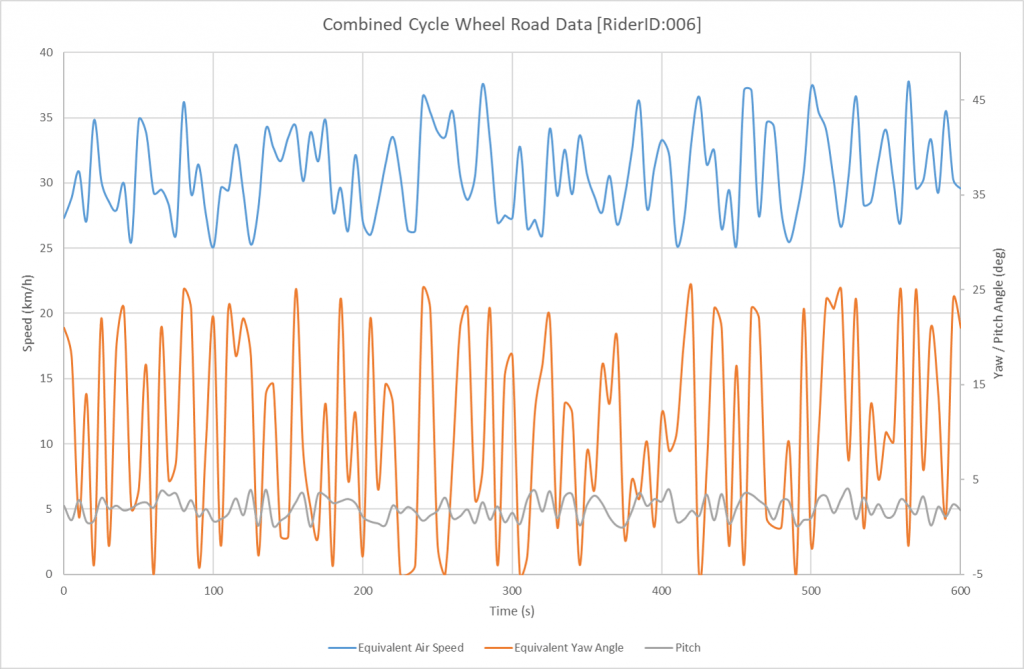
The graph below shows a sample of one ride where a rider was riding along a straight road at an almost constant speed. It is clear that neither air speed or yaw angle were constant.
The real world basis for this protocol are based on two subsets of bike riders in the Bristol (UK) area. Riders who are good club riders averaging 30km/h and time triallists averaging 50km/h. Data from their rides in terms of effective yaw angles, speed and air pressure distribution was recorded over 6 months. This was assessed, aggregated and mapped to a protocol suitable for a wind tunnel. The method of transformation was to statistically analyze the road conditions, apply a Fast Fourier Transformation to the data and run some test simulations for validation. The two discreet protocols are shown below.
THE GRAPHS DO NOT REPRESENT A RIDE CYCLE, THEY INDICATE THE PARAMETERS THE WHEELS WERE TESTED TO. Wind tunnels have limitations and part of the data gathering exercise is to validate data as it’s being processed. It is expensive and time consuming to rectify errors later. To replicate transient conditions, pulsing velocity or pulsing angle are both acceptable. The ramp tests were used to validate one against the other for each wheelset.
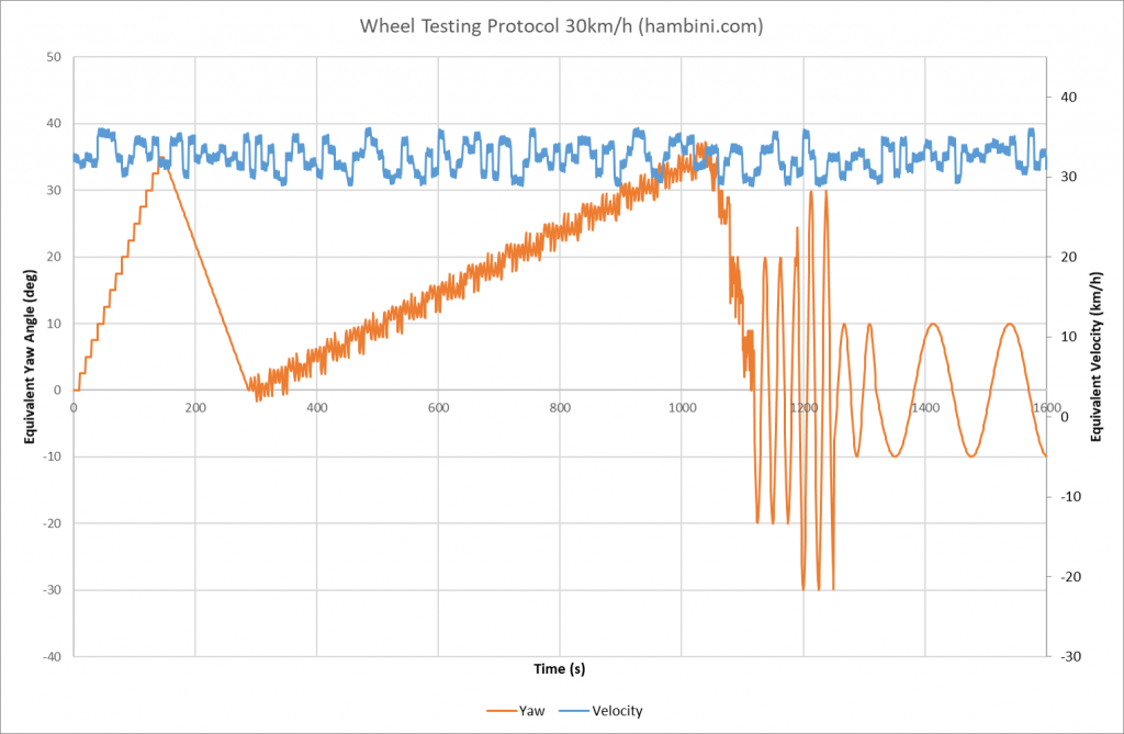
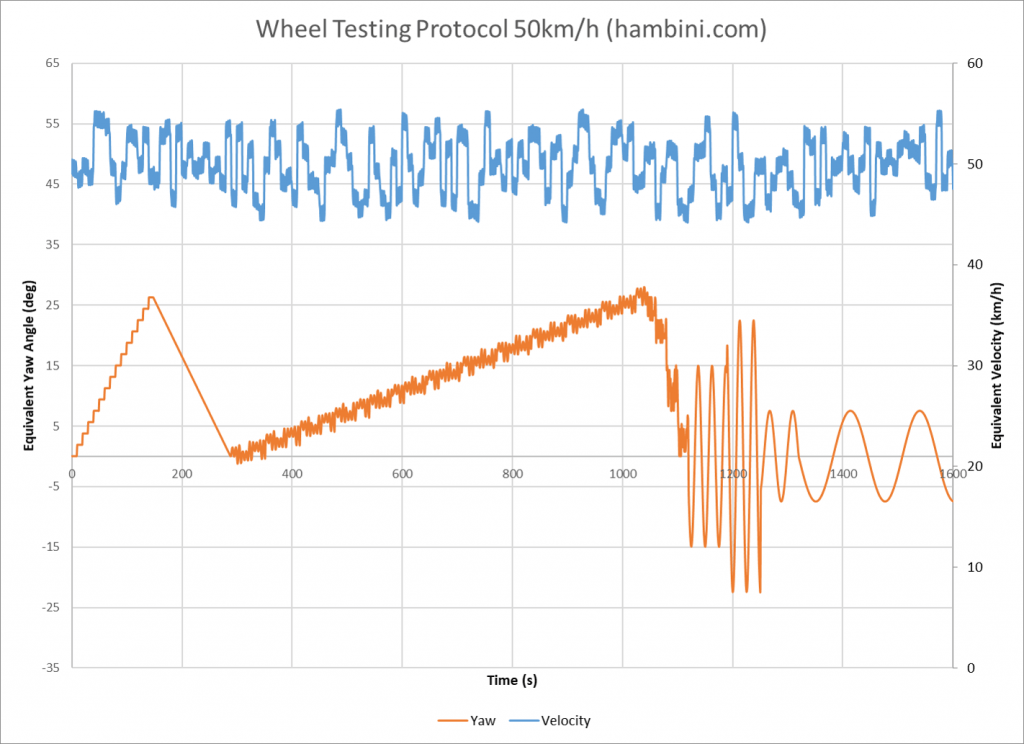
Through investigation it was found that micro corrections from the riders and the somewhat random nature of wind speed and deviation in yaw angle produced transient response of the bike and rider combination. This was much worse on the wheels as they were rotating into an oncoming airstream. In effect, a rider riding in a perfectly straight line into an oncoming wind was generating turbulence/buffeting/flutter by the bike rocking from side to side. What would be considered a zero degree yaw angle in steady state analysis behaves more like 5-6 degrees when the transient effects are factored in.
This protocol mimics the buffeting nature of the rider in the airstream configuration and produces an overall average drag value against time and consequently average power. It is designed to weed out the wheels that have poor transient performance. The lines on the protocols are shown for completeness, they do not mean this protocol favours blustery conditions.
Transient vs Steady State drag
The concept of transient drag effects have been well noted in low speed Aerospace applications such as military reconnaissance drones. This transient concept has not been applied to bicycle related products despite the overwhelming sensitivity of the velocity vectors involved. As an example the crosswind velocity on a bike often exceeds the forward velocity (Ratio > 1). A comparison for a car would yield a forward to crosswind ratio of 0.25 at 100km/h typical cruising speed.
A significant hurdle with trying to accurately measure the drag of a bicycle and rider is the discontinuation of the body. There are large areas with no solid body (eg wheel rim to hub, frame tube triangles, clearances between tyres and frames). This leads to inevitable separation of the freestream from the body surface and results in aerodynamic buffeting or aeroelastic effects (flutter). This causes the flow to take a long time to settle out and inevitably in that time, another variable has changed and the process repeats.
To illustrate the impact of transient drag, the graph below shows the yaw angle which is incremented in step inputs by 2 degrees every 10 seconds (data labels shown). This is plotted against drag force in steady state and in transient states.
The steady state line shows the drag performance of the wheelset when readings are allowed to settle and then noted.
The transient lines are more representative of real life. In the case of this data acquisition, a datum yaw angle was established and 2.5 deg/s of movement was overlapped. As the oscillation was introduced, there was an immediate increase in drag on both sets of wheels. At 4 degrees of yaw, there was a noticeable difference between the Reynolds and FLO wheels. The Reynolds wheels were able to deal with the instability and buffeting much better than the FLO wheels. Beyond 12 degrees, neither wheel was able to effectively contain the buffeting and full separation occurs.
In almost every case, the drag in the real world is much more than in a steady state scenario. It is particularly prevalent on the wheels because they are rotating and the net velocity at the top of the wheels are double the forward velocity.

Time spent at varying Yaw Angles
Whilst the primary aim of this study was to establish a wind tunnel protocol to depict road analysis. Some of the data gathered could be used for generic calculations.
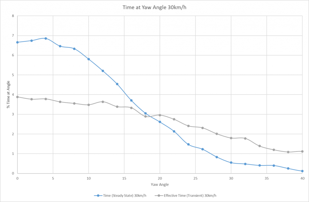
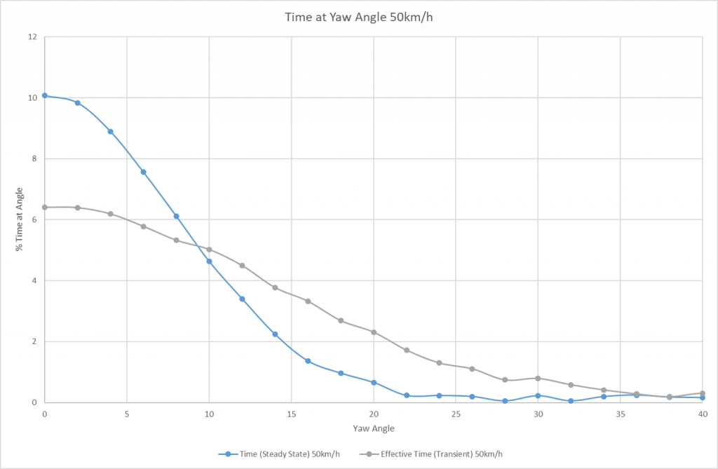
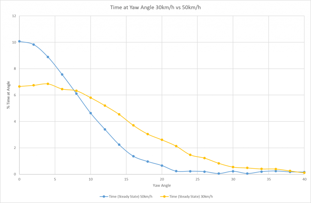
The instrumentation used for the road analysis had a sampling rate of 1024 times per second. Combining this level of accuracy with standard filtering protocols, it was possible to ascertain the effective yaw angle of the bike and rider. By reducing the resolution, the data was converted into a format that aligns with wheel manufacturer marketing departments for yaw angle vs time at that angle. In doing so, it reduced the accuracy of the results but has been shown for comparison purposes.
It should be noted that the transient data was a better reflection of actual time at an angle as it took into account the micro corrections for rider input steering and the instantaneous corrections for wind speed. Filtering for steady state by reducing the sample rate removed the instability. In summary the drag response against rate of change of yaw angle is a better predictor of response in a free stream at angles below the separation point of the section.
When considering an entire bike and rider combination, the effect of the wheels are comparatively small compared to the drag caused by the rider so the transient nature of the wheel drag becomes diminished. The rider drag is by far the dominant part of the system. The effects of transient response diminish as the ratio of forward to swirl (crosswind) velocity becomes greater. Thus the faster the rider goes, the less effect the transient behaviour becomes.
The effect of Tyre width on Aerodynamic performance
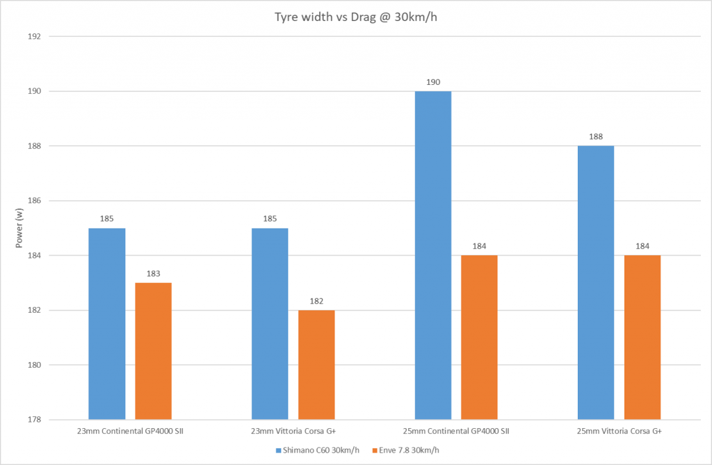
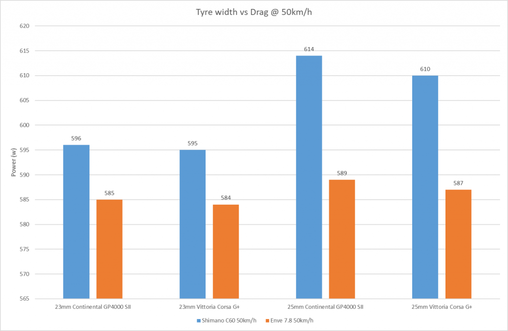
There has been a general trend towards wider tyres in the bicycle industry over recent years. This has been largely pushed by tyre and wheel manufacturers heading towards tubeless designs on the premise that a wider tyre has lower rolling resistance. Whilst the effects of rolling resistance and a more favourable contact patch have been well documented, the effect on aerodynamic drag has been disputed. Some wheel manufacturers have claimed their wheels were more aerodynamic with wider tyres – for this claim to be valid the wheels would have required a lower combined drag coefficient to overcome the increase in frontal area.
The graphs below show the comparison between two wheels, a narrow bodied Shimano C60 and a wider bodied Enve 7.8. It was clearly evident that a ballooned tyre (25mm on a Shimano C60 rim) had a significant impact on drag, especially at higher speeds. In contrast the effect on the wider bodied Enve wheel was much less dramatic. In both cases a narrow tyre reduced the drag. The continental tyres tended to measure slightly wider than their stated width when mounted.
Interpretation of the data
This data should be interpreted like those of fuel consumption figures for a car. They are designed to give a typical indication of how much power is absorbed over an ENTIRE ride loop at a given speed. It is important to note that wheels that are fast at 50km/h aren’t necessarily the fastest at 30km/h.
- The MAXIMUM EXPERIMENTAL ERROR has been calculated at +/- 2.5%, the middle of the range is plotted for each of the values to maintain consistency
- The rim depths are split into classes to make it easier for comparison, they may not agree with the stated size from the supplier.
- The Power rating in a transient analysis is much worse than a steady state analysis
- Comments are indicated for anything noteworthy
- The rider position was within +/-10mm for each run, this was backed up with a reverse mounted pressure rake to remove any spurious data. There have been comments suggesting a rider could not keep a fixed position for the entire cycle duration – the protocol does not require them to, error checking is built in. Although unusual for the cycling industry, removal of appendage drag is commonplace in the Aerospace industry so the same technique was applied
- Control Tyre was a pair of Continental GP4000SII 23mm with a pressure of 8.25BarG, there are two wheel combinations that differ from OE, these are a modified Borg wheel and a Mavic Tubular.
- The ROTATIONAL Drag required to spin the wheel up is included (Most manufacturers do not include this figure which is around 25 to 30 percent, a notable exception is Swiss Side)
- The riding position (relaxed hoods) remained unchanged irrespective of speed. In reality high speeds would necessitate a different riding position but doing so would have invalidated the test.
NOTE UPDATED GRAPHS ARE HERE


Who tests in Transient Conditions?
To date, the only company that has confirmed they test for and include turbulence (transient conditions) when designing is SwissSide. Jean-Paul Ballade of SwissSide commented on the Youtube video shown above.
Although unconfirmed, there are certain features on Mavic wheels which suggest they either design for or test in Turbulent conditions.
Conclusions
Riders have long been fed a diet of wheels being tested at 50km/h, this speed is inappropriate for the vast majority of riders as they cannot maintain the power required for that velocity. There has been a general thought process that most riding happens at yaw angles of less than 10 degrees. Whilst this may be a valid statement if you are doing 50km/h, at more modest speeds this does not occur. In both 50km/h and 30km/h riding, the effect of micro corrections to the steering, turbulence from the wind itself and external objects causes unsteady turbulent flow over the wheels. This phenomena causes the effective yaw angle experienced by the wheels to increase.
- Wheels that performed well were noticeably resistant to generating areas of turbulence
- Wheels that performed well mitigated generated turbulence quite well
- Wheels that performed well had a lower rotational drag compared to their competition
- Wheels with a deeper rim section are generally more aerodynamic than shallow sections
- The difference between wheels of a similar depth is very small and it would be difficult for a human to be able to detect this during riding
- The difference between a low profile wheel and a deep wheel would be picked up by a human riding.
- The FLO cycling and Hunt wheels performed badly, they appear to have been designed by individuals with a limited understanding of aerodynamics of rotating objects. As such they generated unnecessary separation and could not deal with the separated airflow
- The Aerocoach disc and 75mm deep section front wheel showed quite interesting results. This wheel was essentially an aluminium wheel with a clip on fairing. At low to moderate speeds, the wheel performed reasonbly but as the speed was increased the wheel started to perform quite erraticaly. The front wheel construction is agriculturual and large gaps exist between the spokes and the non structural fairing. These gaps generated pressure disturbances and caused the flow to behave erratically. As the speed was increased, it’s performance became quite poor in comparison to the immediate competition and this was mainly due to the poor front wheel design. A picture of the problem is shown below
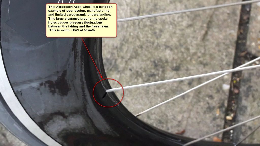
If you are considering using the data from this article to influence your purchasing decision then please use this with caution. Some aspects of wheels like their general build quality, braking performance, hubs and ease of maintenance are not measured. These factors should be taken into account accordingly.
Flo Cycling examined in more detail…
After publishing this data, some people commented the data was controversial. In the sense the brands they expected to be good weren’t. Of note was Flo Cycling. A brand that is run by two Canadian Entrepreneurs from their base in Las Vegas, they buy in rims from the far east and sell them with their markup to consumers around the world. Some further anlysis was conducted into the aerodynamics by Airbus aerodynamacists and the conclusion was unanimous.
It appears that Flo Cycling did not model or take into account the effect of the spokes on their wheels. The spokes and internal geometry contributes up to 40% of the total drag – the amount decreases as the wheels get deeper. Their wheels had very poor aerodynamic behaviour aft of the wheel rim.
FLO were asked if this accusation was true on several occasions, and on each occasion, they have declined to respond.
FLO’s marketing has a heavy engineering bias and to the untrained eye, this reads well. However when looking at their hub design, the calculations behind them and their engineering practices some gaping holes were noted.
When looking at this page Flo Cycling (Update: They deleted it so here’s a copy that was downloaded for evidence). It was quite obvious that the engineering behind flo wheels is commercially driven and not mechanically driven. Topics of note
- The choice of measuring tool – a vernier caliper is totally unsuitable for measuring down to 0.01mm
- The L10 calculation does not account for any axial loading in the bearing, to put this into layman’s terms, it does not account for the wheel going around corners or being subject to road vibration
- If the bearing met ISO, JIS or DIN standards, it would not measure an exact mm reading, it would be slightly under (i.e. 20mm nominal is 19.99mm). This highlights the use of a poor measuring instrument or poor quality bearings
- EZO bearings have only been chosen because the hub supplier in Taiwan uses them as an upgrade over the no name standard bearings they use. EZO bearings have been chosen for commercial reasons not technical reasons.
Here is what NTN technical had to say
The calculation provided from this page does not approximate the road behaviour of a wheel bearing with sufficient accuracy. One would expect to see the axial loads applied with a ramp or step input along with sinusoidal input for the radial loading. We would not expect the wheel bearing to last as long as the L10 life predicts because the boundary conditions for the data are inaccurate. Further, vernier calipers are not recommended by NTN for the measurement of our bearings, we cannot comment for other manufacturers.
FOLLOW UP… Letters from Lawyers
Shortly after writing this blog post, I received a letter from a firm of solicitors representing FLO cycling which was addressed to the HR department of my employer. They complained this page depicted their wheels in a poor light, the test protocol was not openly published and they did not like the statement that they had a limited understanding of the aerodynamics of rotating objects. They wanted their power figures removed from the data along with threats of court action. Furthermore, they requested I was dismissed from my Engineering position for misuse of company resources.
It should be noted that FLO Cycling have a somewhat questionable strategy of paying prominent forum members in a number of popular cycling/tri forums to endorse their products. They usually do this under the premise of supplying wheels.
FLO cycling’s behaviour has been disappointing as when the wheels were originally tested and an issue was found, FLO were contacted. This was 6 weeks prior to the data being uploaded. Once the data had been uploaded, they were first to comment and question every aspect of the testing in surgical detail, even going so far as to suggest an adjustment of 5% in tyre pressure would make their wheels more aerodynamic. As time has progressed, they have come out and openly stated that these results were fabricated.


I can see this list of wheels is growing, I was just wondering whether you’d managed to source a set of the Giant SLR 55mm wheels locally? And if you’re still expanding on this frankly awesome test Please keep up the good work!
I may have forgotten from the previous video you’ve made, but do 2-5 spoke wheels cause less drag than traditionally-spoked wheels due to more surface area for air to attache itself, or would its thicker leading/trailing edge create drag with similar amount?
Love your work (although now I need new wheels AGAIN! Haha)
Regarding 23mm vs 25mm drag difference – does it really results in significant frontal area difference on wide (e.g. 29mm Enve 7.8) rims and might larger tire reduce flutter if rim is “optimized” for 25mm?
Thank you so much for publishing this incredibly precious collection of data! Having been working in CFD sims for about a decade myself I can only imagine how much work went into measuring all this. Thank you!!
Quick question, I was looking for the planetx disc wheel you tested in this article, but could only find a selcof disc on the planetx webpage. Is that the wheel you tested?
Thanks again and keep up the great work!
Ferdinand
Could you comment on why in your view the Hunt wheels performed so poorly? (Especially the 50mm, which I would have expected to do better purely due to its depth.) Find that one hard to believe, considering it was designed by Luisa Grappone, an Aero engineer formerly of Campag, and the Bora One does so much better.
Do wonder if they are designed for a 25mm tyre, and testing with a 23mm is sub-optimal (but you’d have to compare to other wheels running a 25mm tyre, as there is the valid point you made about the unavoidable impact on frontal resistance with a wider tyre).
Thanks for sharing valuable data Hambini.
Could you tell me which part is updated in the last post? Now I can’t remember the entire list of the tested wheels.
Would you happen to know if the Aeolus wheels in the test were the older versions with Rolf/paired spoke patterns or the newer versions? Thank you!
Has Hunt commented on these results? I’m interested in what they have to say. They are good value though and well built!
No hed gt3 in this test. I have one and im curious. Its an awesome wheel.
Hi Hambini,
Great work and fair play to you for sticking your head above the parapet.
I’ve the same question as William Kin. Is it worth going deep section at all when using a gravel tire, upwards of say 38mm, when the widest rim I can find is the ENVE SES 4.5 AR @ 31mm. Does the tyre bulge negate the deep section rim in terms of aero advantage?
I am heading over from the UK to take part in the Dirty Kanza 200 and am really unsure if I should go deep section or just stick to a nice light set of traditional gravel/mountain bike rims.
Average speed around 15mph but a number of hours I suspect over 20mph in total.
Many thanks
Julian
Hello,
I am the happy owner of one of your Bottom Bracket and I thank You Tubes’ algorithm who pushed me your videos while I was looking at ceramic speed ones alleluia !
I very much liked the level of explanations you gave here. The audiophile comparison makes a lot of sense !
Instead of asking another please test my wheel I have got a general question about disc wheels, deeper rims and crosswinds for small riders. I am a light triathlete at 62 kg 136 pounds and the challenge of a time trial in flat open terrain is mine. I am not the Tom Dumoulin body type. So when can we say that a light rider could take advantage of deeper rims on front and a disc wheel ? I would say that I can ride 90 km in a good TT position around 200W so that makes between 33 and 36 km/h average depending on elevation.
Thank you
PS wirting my question I get that my question is not so “general” and quite personal
Any idea how the Yoeleo C88 would fare against the Zipp 808 at 40km/h?. It seems to be right up there with the best at 30kmh but falls behind at 50kmh.
what is the width at the rim and width at the widest point on the yoeleo C50s, as it looks as though you can get them in a number of widths.
EDIT: It looks like you answered this on the forum stating it was a 25mm width. Would i be correct in assuming a 27mm width at the brake track have a better result?
Very interesting data and thank you for doing a real life, no bullshit testing can feedback. From my understanding basically if you are not getting regular speed around 50kph then it is better have a light pair of wheels with a good hub. Are there any specific rims out there that is the most suitable? Thank you for your time.
Hi, would it be possible to test a wheel with a kinlin XR31T rim (31mm deep, 24mm wide, 19mm internal), hunt aero wide, borg31 or any wheel with these rims.
They seem a cheapish choice that can be handbuilt with choice of spokesand hubs, so do interest me a lot, but not if they are a poor aero rim!
Many thanks, appreciate it may be a while, if at all.
Since you decided to repost this article, I figured I’d post a link to the following article in response to all of your allegations.
https://flocycling.com/blog…
Chis
Hey thanks for the great job!
Could you please clarify if the Aeolus 50mm is the Bontrager Aeolus XXX 4 or the much cheaper Bontrager Aeolus Pro 5? If the former, how would the Aeolus Pro 5 perform? Thanks!
I also would like to know which Aeolus rim was used.
Hi Hambini,
Thanks for doing all of this. I was wondering if you were planning on updating this with the prime black edition wheels? I was looking to buy a pair but want to see if it is worth it or if I should go with the older models. Thanks for making this blog it is really helpful, to cut through the marketing crap! Also please do one on aero frames, that would be incredibly interesting!
Thanks for keeping this active!
I’m curious to know how the Campagnolo Zonda C17 performs in comparison with the Campagnolo Bora 35 clinchers (shod with the same tyres) and think this will be an interesting test for a number of reasons:
1) The Zonda C17’s and Bora (35 and 50) share the number of spokes front and rear
2) The Zonda C17’s and Bora (35 and 50) have identical flange design front and rear
3) Both Zonda’s and Bora’s use exactly the same spokes and nipples (albeit at a slightly shorter length for the shallower alloy rim in Zonda’s case)
4) The internal rim width of the two is identical (17.2mm) and the external rim width is within 2mm (22.5 on Zonda and 24.2 on Bora)
5) The Zonda is 1/4 the price of the Bora.
A suite of tests (aero being your domain) and stiffness numbers from Tour Mag will mean any performance difference comes down to the rim, the whole rim and nothing but the rim.
What would be a back of fag packet for rim depth to width ratio? I.e. to identify rims that have an alpha angle beyond alpha crit? It’s such a minefield… So many deep rims to choose from. and don’t get me started on tubeless ready rims which are impossible to get clinchers on to!
Great post and video. I was wondering about one thing, though, that I haven’t seen you mention explicitly: the inside of the rim is a trailing and a leading edge at the same time (on the front and rear side of each wheel). As far as I understand, that is why modern aero wheels no longer use simple NACA profiles for the rim (3T explicitly mentions that on their web page). So for example when you explain your rule of thumb of rim depth to tire width, wouldn’t you have to also consider the situation at the back side separately (where the inside of the rim becomes the leading edge and the tire the trailing edge)? And what about optimizing the rim profile, what balance should you strike here between front and back side?
Thanks for update, Mavic Comete next please please
Awesome work!
Would be spectacular if you could test the Reynolds Strike, also the DT swiss 1400 series and a more modern “semi aero” aluminium rim as a baseline, something like a DT swiss r23 or so which might be more representative in terms of what many people would be moving from, rather than the boxiest box section rim there is.
can you add standard deviation bars to your graphs? 2.5% error is a lot when you consider the difference here, a lot of these rims start to look equivalent here then, sans a few of the poor performers such as flo or hunt
The Enve 7.8 are listed as 70 mm — but I assume this was a standard set of 7.8 where the front is 71 mm deep and the rear is 78 mm deep?
A question re your comment that a 23 mm is more aero even if the wheel is optimized for a 25 mm tire (as is the case with the Enve 7.8) — I believe this to be true for a clincher where the tire at the bead part automatically gets as wide as the internal width of the rim, but I doubt that this can be true for the tubular version of a wheel. Take again the Enve 7.8. The front is 29 mm wide (another 3 mm wider than a Zipp 808) and the rear is 27.5 mm wide. Like you point out elsewhere on the page, the tire to rim interface is important enough that Mavic tried to place a plastic cover there and that filling up this gap may help. When a 23 mm Vittoria G+ tubular tire is installed on a front Enve 7.8 tubular rim, the rim bed is substantially wider than the part of the basetape that comes in contact with the bed. In other words, on both sides of the 23 mm tire there is 2 mm of carbon forming a very un-aero “lip” on each side of the tire (the air sees not just a tire but also an additional carbon protrusion on both sides of the tire). Wouldn’t you think that in such a case, a 25 mm tire will actually offer both better aero specs (due to better tire to rim interface) AND better rolling resistance? Thanks for all the info!!!
Standardizing the tire across the board is not valid. I own hed Jet 6+ wheels for example. For those wheels to be aero optimized tires should be selected to match the wheel. The Hed Jet 6+ measures 25 mm at the rim bead. Putting on a 23 mm Conti will get you a tire that is wider than 25 mm, and will degrade the performance of the wheels. Other wheels such as the Campagnolo Bora will face a similar problem. For your results to be meaningful you should be matching the wheel with proper tires.
Agree with you Jeff. Though standardising the tyres may sound like the elimination of variables, it’s not. They should be tested with the recommended width but the same brand and model.
A 25mm tire isn’t going to be aerodynamically faster than a 23mm regardless of manufacturer recommendation. If a 23mm nominal balloons to wider than 25mm on a given wheel, the 25mm will invariably balloon to over 27mm.
Very good read thank you!
Wish you could have had some Campagnolo Wheels in there too…especially the new WTO series
Great read, thanks, and I have a specific question if you have the time. When I was aero tested in a wind tunnel earlier in the year, they gave me a fairly consistent CdA figure of 0.25 riding on the drops for my track setup (Dolan Pre Cursa non-aero bike, skinsuit, regular helmet, deep section 80mm clinchers with 25mm Corsa G+). Recently when I was doing some solo efforts at the Manchester velodrome I found that my average power for two laps on the black line at 17s/lap (just under 53 kph) was 575w, which gives an implied CdA of 0.27 (Assuming Air density 1.226, Crr 0.004) . I just realized after reading your article that you are actually doing a 360-degree turn on each lap around a velodrome, so the yaw angle around the bends must be quite significant. Do you think the mismatch (0.25 vs 0.27 CdA) could be accounted for by the yaw, or could the differences in conditions and that my Crr is really just a guess, account for the differences?
Hi ka314159, I think your question can be answered in the negative on the strength of very basic geometric reasoning. Your velodrome has a 250 m track, and while i could not find the precise radius of the curved ends it is unlikely to be less than 23 m. This gives you a curvature of 2.5 degrees per meter of track.
a. Assuming your wheelbase is 1 meter and that you travelled along the track at such a glacially slow speed that there is no centripetal component at all, you steering input in the curved sections would also be 2.5 degrees. In reality you will be going quite fast, banked strongly in the curves, and your steering input will be almost imperceptible. The vector difference due to track curvature will still be there but, distributed between front and rear and further diminished by the tilt of the bike, I expect the actual impact of track curvature on angle of incidence to be about 1 degree or less, which will have a very small effect on air drag.
b. Assuming you have 46cm of shoulder width, your right arm will slice the air about 2% faster than your left arm in the curved track sections. This corresponds to a 4% difference in drag between your left and right, but that is the extreme difference and for the whole body the differences will mostly cancel out. I certainly cannot imagine whole-body drag in the curved sections of the track being more than a fraction of a percentage point higher than in the straights.
c. Therefore, the 8% difference between the 0.25 and 0.27 coefficients cannot be attributed to yaw or to the curvature of the track.
Hope this helps. Better still, I hope our gentle host steps in and blows my analysis to bits.
Seems to me that since the most gain is to be had from a larger/deeper profile, I think the best thing to do for those looking for an aerodynamic upgrade is not another set of wheels but rather a set of side walls that clip snugly onto the existing wheel combined with 23mm tyres. Since such clip on side walls do not exist (at least that I know of) , I see this as a strong marketing opportunity for some inventive person/s. I might even do it myself. Since there are so many existing wheels out there,the potential market could be quite large.
Appreciate this work Hambini, my goto now when looking at wheels!
Any thoughts on the new graphic design Zipp 404 v the previous version? Thinking a ‘nearly new’ second hand set of the slightly older version is probably good speed for the money now (disc brake).
The new one is not going to be much faster if at all versus the ld one. I’d save the peniies and get the older type.
So informative Hambini!! Love the vids. What are your thoughts on the new HUNT Aerodynamicist wheel in 52?
Bradley Wiggins did the hour record in the Velodrome pushing 440W for 1 hr, averaging 53km/hr. How do we justify the power difference compared to the one on your test, riding at 50km/hr? Does the optimisation of wheelset, position, clothing and bike justify the whopping power difference?
I won’t speak for Hambini, but I’d think that was because Wiggins did that ride in an indoor velodrome, where you essentially reduce/remove many of the (cross)wind and drag effects that you would encounter outdoors – effects that these tests were specifically set up to investigate.
The drag difference from relaxed hoods to TT position would be 100W at that speed, so that’s the vast majority of it.
Am I right that the power only account aerodynamic losses?
In this case approx 60 W should be added for rolling resistance (P ~ Crr * total_mass * 9,81 * v) @ 50 km/h, correct?
Thanks for continuing your great work!
Probably tried of the comments here by now, but an interesting one came up..
The new Roval Rapides have a V shaped narrower rear, and a wider internal front with a U shaped rim. Specialized claim these to be very quick.
Hunt however have this similar design previously, and Hunt’s tested poorly here. Is it possible that two similar designs can test quite differently? Can the execution make much difference?
Blair, one thing to consider is that the Hunts are designed to be fitted with a 25mm tyre but they are tested with a 23mm tyre here. It may sound marginal (and probably is) but it’s something to consider.
I would love to hear your thoughts on if deep section wheels are worthwhile on gravel bikes where the tires are 35c or greater. If you can’t match the width of the tire is there any point in bothering with deep section rims (eg. 35 tire on 32 rim and a section of up to 65mm)? Or from what I understand even if you could match the tire width to the rim width the section would need to be greater than 80mm?
Interesting article! It’s so important for the field to take into account practical road conditions. Have you published this work in a peer reviewed journal?
But ia is a cheap used set of Flo 90 Still Faster then my box stock rims for a 38 kmh rider
it depends what your box stock wheels are.
Which Aliexpress 3spoke wheels did you test? Is it possible to indicate the manufacturer? Thanks
Superb information and very interesting!
Might be nice to add the rim and tyre width measurements with tyre width effect graph, I found:
Enve 7.8 are 29mm wide front 27.5mm rear
Shimano C60 are 22.4mm wide
It is mentioned spoke holes have an effect when using hidden spokes. Could it be beneficial to kit-up all the holes in the rim with flexible acrylate kit?
Acrylate kit is easily available as painters kit in a hardware store and with a finger and some dish washing liquid can be finished very smooth. Or would imperfections in kitting very soon dwarf any gains that could be made that way.
And there is always a ridge between the tyre and rim where they meet. Regardless of clincher or tubular tyre it is there. Especially with tubular tyres, which are meant not to take off unless punctured, would filling the ridge between rim and tyre with acrylate kit help? Is there any estimation of an bandwidth of aero advantage that could be reached that way?
Most tyres are wider than the rims, for example a 23mm tyre in front on a 22mm rim. And a 25 mm tyre in the rear on the same 22mm rim.
Sometimes these kind of small things can give big effects, so it would be interesting to know.
For the widths, this was considered but the manufacturers are changing their patterns with model years and hence this would have become to problematic. Silicone sealant has been shown to work, that dip which is technically called a discontinuity can be used advantageously like in the winspace wheels but more often than not it’s a negative.
With a graph of detailed power effects of rim/tyre width combinations, it is clearer if the measured width of the rim and tyre are given. Exactly because the specs vary over the years.
Stiff Silicone kit or more flexible Acrylate kit, which would be more compatible with: carbon rim, tyre rubber and tubular glue?
Within which bandwidth could the expected aero gains be of kitting the ridge (discontinuity) between tyre and rim be expected to be? Zero to ???? watts at 30km/h or 50km/h
There was once a firm selling strips to fill the gap, but the Cycling union banned it. But kitting is 100% legal.
Mavic had the cx01 blades.
You could clip them between tyre and rim to smooth the transition between tyre and rim for better aero.
I have not seen test data but Mavic predicted HUGE aerodynamic gains. The fact they banned it because every manufacturer would have to develop something similar can indicate that it works.
Good for every tyre system but especially tubular, since most people leave them on the rim for a while and the gap might be bigger.
The big issue is which kit to use. And how much of the void to fill up. The last question is something for an aero engineer like Hambini (wink wink).
What goes well with the tyre glue? Is Silicone a bit stiff for a flexing tyre? And how do more supple fillers go together with other materials?
So professional wheels article!if you want the wheels faster,a good quality rim and spokes is necessary.
Without photos or a weblink of the unbranded wheels the results are pointless. EXACTLY which aliexpress 3 spoke and disc? How can the results be trusted if the top performing wheel combination remains unknown. It seems from your test that any anonymous Chinese wheels will perform better than the latest aerocoach stuff for example that is used by world tour teams.
A disc wheel is efficient because it limits the amount of leakage – it’s a solid boundary which air cannot permeate. The 3 star disc is available in a number of different brand names. the brand tested was deerocatcher but the same wheel is on aliexpress with a different brands. The Aerocoach front wheel is efficient because it is deep. When the section becomes deeper, all aerodynamic solutions will converge so there will be little to choose between them.
yep, very sus…btw I want those fast wheels plz.
I’ve been looking into getting my first ever wheel upgrade and am a fan of this channel to sus out what is real vs bs vs marketing.
One brand I’m considering is lightbicycle and I noticed they have this new design that they call “x-flow profile”: https://www.lightbicycle.com/newsletter/Introducing-Falcon-Pro-AR375—AR465.html
Do you think this is legit? just marketing? or probably aero-harmful? Also when building custom wheels from LB, you have the option for drain holes. Do you think drain holes are good or just more risk of contamination inside the wheel and more aero harm?
@50kph+ I need all the help I can get, so wheels that aero at that speed are all good. I think that the conclusions got a bit hijacked by Flo.
It would be better to talk more about your results, and have a separate article with a graph of bs vs manufacturer in it.
Hi,
Just wondering if you have the chance to test wheels from TokyoWheels, looking at Epic 5.6. It has claimed to be quite a all rounder wheels etc. It has some controversy On some forum, and the boss, James, even sent their wheels for evaluation.
If I get hold of some I will test them.
Caden Wheels are seemingly very impressive for the price and weight/build quality. Would love if you could get a hold of some for testing. Thanks!
I think they are the same as a set of Trifox ones I have.
I see that Hunt now has the 50 UD carbon spoke wheel set, which is obviously the Winspace 50 2020 wheel set that you tested. Looks exactly the same, same width, 26mm, and depth. They obviously look exactly the same, and to top it off same exact weight. Hunt has them on the warranty though. More importantly though, which wheel has the least annoying sounding rear hub?? I need less if not quieter bees below my knees! Better yet what grease makes an annoying freehub body quieter with out creating too much drag or friction?
It might not be the same. The KPS wheels look very similar to the Winspace but on measuring they are not the same.
Just keep pedalling and your freehub will stop buzzing at you.
Thanks for this good data – deeply appreciated. Will using 23mm GP5000 climcher tyres vs 25mm GP5000 clincher tyres negatively affect the discontinuity of my Winspace 50mm wheels ? Your video review of these wheels gave me the assurance to purchase them, thanks.
yes, the larger radius and lower max pressure on the bigger diameter tyre will have a negative impact.
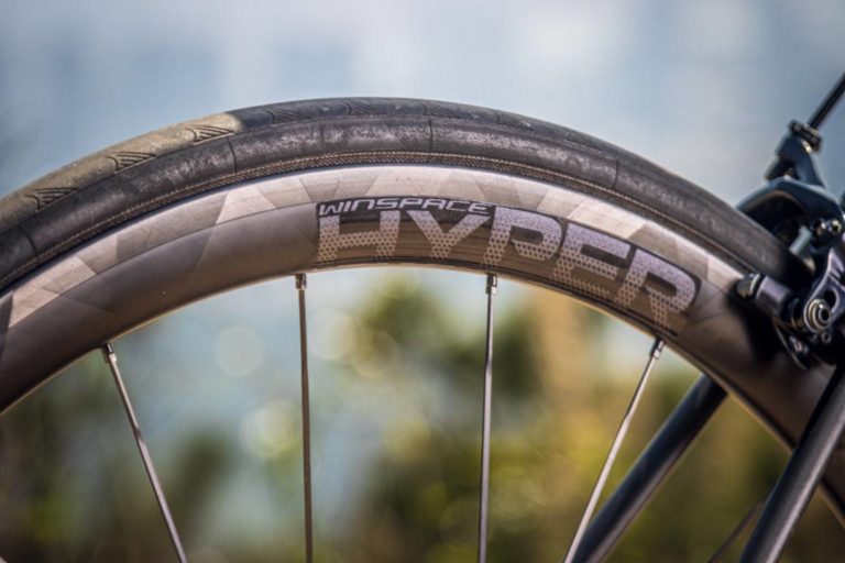
Hi, thanks for this interesting and useful information. I was wondering, the Winspace 50s are obviously very good, but do you know the Winspace Hyper 38s stack up against the lower performing 50s and shallower depths?
I couldn’t comment.
Thanks for a great post, but it doesn’t bringing up disc wheels so I wonder what your take is on these? Specifically as some brands use non-flat profiles on one/both sides of the wheel (e.g. black inc zero and aerocoach aeox orbit). Compared to more traditional discs wheels, where the sides were completely flat and symetric on both sides. And the middle-ground, such as princeton carbon works blur and vision metron disc, which more look like a traditional 60-80mm rim but covering up the spokes with a separate section (which sort of introduce a kink where these intersect as they have different angles). Without having any way of testing these out before buying them, which type of wheel would you go for? Is there any merit to the brands statements that these newer shapes improve stability or revolutionize the field (kind of a leading question, as I assume it doesn’t)? I understand if there is no good answer as interaction with frame/disc break rotor etc can have a large impact on the aerodynamics, but would be interesting to hear your thoughts.
have you done, or are you aware of, a study of the benefit of a lighter wheel rim on acceleration (e.g. watt differences? Thanks
Does the depth of the tri spoke matter? What are the difference between a 70mm or 60mm tri spoke wheel?
it will make a difference, the deeper it is, the faster it is.
What’s the difference between 42mm and 50mm tires?
Cycling enthusiasts and competitive riders will find this blog post fascinating. It delves into the science and testing behind finding the fastest bicycle wheels, shedding light on the pursuit of speed in the cycling world. It’s a testament to the meticulous attention to detail that goes into optimizing equipment for performance.
Thanks to your thorough research, I have able to race to several podium finishes on a family friendly equipment budget with a Yoeleo RX88/D3 disc combo for the past 4 years! The cycling industry has continued to flush the market with new gear and I am curious if the new developments in the wheel sector have shifted anything, if there are some real improvements, or if it is mostly marketing smoke and mirrors?
For a lot of realworld cyclists we want comfort with speed and still climbs well/ok. In the uk our roads are shit, I’ve had a few nasty crashes as a result of them. I’m 64kgs and used to be a reasonably fast cyclist and a good climber but not so much now as age has caught up with me but still do 50-80mile rides at around 17mph avg. I wanted to change my 35mm hollowgram wheels with 25mm tyres for something that has been designed for up to 30mm tyres tubeless that is going to give me that comfort/speed/climbing with destroying my bank balance. I’m ok with spending around the £1500 mark if needs be. Have you come across anything that will do this? Hunt do a new sub 50 but I know you really don’t rate them. Elitewheels Drive D50 is nice but only 28mm. They do do a new helix 46D or 57D that is possible although it’s got a wobbly internal rim which I’m unsure about? I’m running into a brick wall here. Maybe this is something you can go to for a future review as I’m sure Im not the only one looking for this kind of wheelset. Keep up the good work. Kind regards Russell scott uk
What is the point of all these aerodynamic power to watts performance graphics with all these name brand wheel comparisons when the wheel(s) in question are completely out of balance..?! That’s like aerodynamically creating the best Passenger By pass fan blade in the world, which will only fail because it was not rotational balanced??
Think about this, so far in the bicycle industry there are no wheel balance standard. You can take 10 wheels which the tire, rim and air-valves were made the same day by the same mold, and all ten when assembled are going to have different balance values. Some will be severely out of balance because all three heavy spots will accidentally be located close to each other causing the wheel to have an extremely heavy spot making wheel balance a lop sided affair. And by sheer luck, some will be fairly balanced because by PURE ACCIDENT all three heavy spots will be somewhat distributed kind of evenly. These three heavy spots are there by manufacturing default on the tire, the rim and the air-valve.
So testing aerodynamics performance on a wheel is completely bias and wrong… You first need to rotation balance a wheel to learn the real and honest aerodynamic performance results. Plain and simple a well balanced wheels spinning at high speeds will always give better results.
FYI: Think about this…. Basically 50% of a bicycle is static, i.e. Frame / Fork / H-bar assm / Saddle assmembly. Mean while the other 50% is spinning at a high rate of speed. Don’t you think if you rotation balanced that spinning 50% the performance is going to be very different..?!
Newton’s 1st Law is like this… A mass that is put in motion, will continue in motion, unless it is interrupted by 2 things, an outside force (i.e. air drag / Aerodynamics). Or on Oscillation (i.e. rotation wheel balance).. An F-1 race car is based on this formula and the only reason bicycle wheels dare not touch the subject of wheel balance is because they have no idea how to create a consumer friendly bicycle wheel balance system..
THAT IS ALL ABOUT TO CHANGE in 2025, stay tuned…
Sincerely, Dan Sotelo