Bearing Extraction: Using Blind Bearing Pullers

Blind bearing pullers were originally designed to remove bearings from holes without rear access. These were primarily found in rotating equipment and commonly in sealed units such as car gearboxes. Of late, they have become popular for the removal of wheel bearings. However, using these items does come with problems that the advocates of this technique are either ignorant of or unaware of.
Bike shops often use these devices because they save significant amounts of time but they are likely to damage wheels without any obvious indication.
What is a Blind Bearing Puller?
A blind bearing puller is a tool designed to remove bearings that are recessed within a housing or machine, where traditional pullers cannot reach. This specialized equipment features a unique mechanism where the pulling arms slide through the centre of the bearing, expand behind it, and then retract to grip the bearing securely from the inside. Once engaged, the puller exerts a steady pulling force, ensuring the bearing is extracted without causing damage to the surrounding area. They come in various sizes and configurations to accommodate different bearing dimensions and applications.
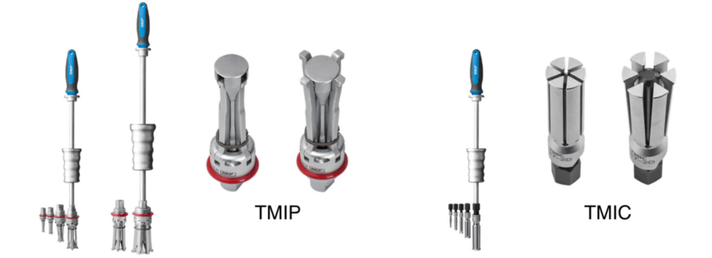
One of the most popular designs is expanding collet types, of which the bearing manufacturer SKF makes a considerable variety. SKF TMIP and TMIC units are widely used throughout industry. These units can be used with a sliding hammer or with a sleeve and threaded rod.
Basic Bicycle Hub Design
The vast majority of bicycle hubs use 4 bearings at the rear hub/freehub and a pair of bearings at the front hub.
At the rear freehub, there is often a pair of deep groove 6000 series ball bearings with an intermediate preload spacer between the two inner races, this is shown arrowed red in the picture below.
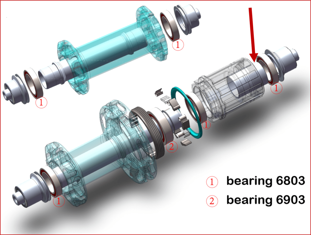
A problem arises because individuals are using blind bearing pullers without any consideration of the damage they may be causing to the intermediate spacer. The spacer sets preload using fixed displacement, it is not adjustable.
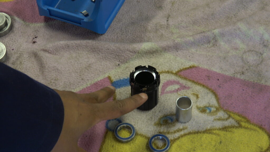
Blind Bearing Puller – Method of Operation
A schematic showing the setup is shown below. This highlights the difference in hardness between the materials and the bearing machining radius, typically of the order of 0.2mm to 0.3mm in series 8,9 for 01,02 and 03 bore bearings.
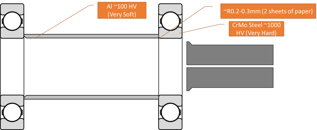
Once the collet has been expanded, the comparatively soft aluminium is preferentially damaged. SKF stated on small bearings, it has a tendency to increase the interference fit into the housing so it may “scrape” during removal.
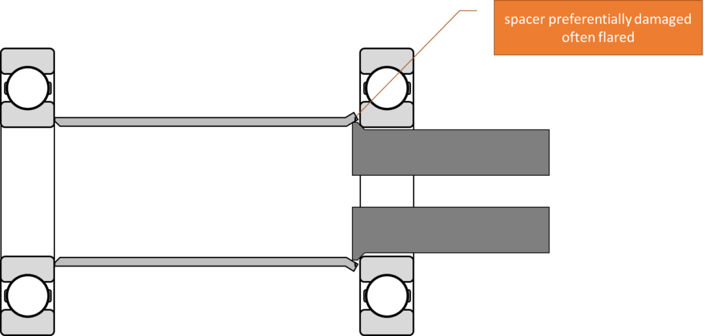
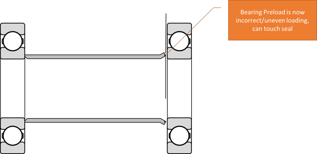
This results in an increased gap between the bearing and the spacer, which results in incorrect preload
SKF specifically give data with their TMIC and TMIP series of bearing extractors, which states a minimum gap of 3mm must be observed behind the bearing to prevent damage. In the case of bearing preload spacers, these are designed to touch the inner race of the bearing and thus the gap is zero. A blind bearing puller is not a suitable extraction device.

The SKF User Manual shows a TMIC extractor protruding out of the blind side of the bearing, which is the reason for the 3mm space requirement. An excerpt is shown below. SKF advise the claw depth is typically 1.5-2.0mm beyond the edge of the bearing.
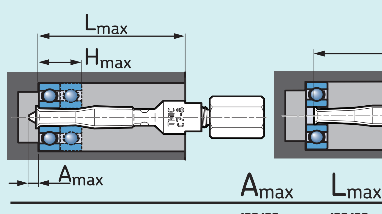
You can download the User Manual Below
NTN have an equivalent bearing extractor, NTN BP Puller series. NTN Specifically warn about the puller teeth and clearance behind the bearing
A Photograph showing the physical protrusion of the puller jaws is shown below.
Raceway Extraction Puller
In situations where there is less than 3mm behind the bearing or a severely reduced gap ie in the case of this touching spacer, a raceway extraction puller should be used. See here. This requires no gap behind the bearing and it does not increase the interference fit on the outer race.

The Response from NTN and SKF
NTN (NTN-SNR) were asked about blind bearing pullers for wheel hub applications, and this was their response.
NTN do not recommend the use of an internal expanding collet bearing remover in any application where there is insufficient clearance behind the bearing. NTN specifies a minimum clearance of 2mm for bearings of less than 17mm bore diameter to facilitate removal. The use of devices with inadequate clearance may result in damage to the bearing or damage to the housing immediately behind the bearing.
NTN do not recommend the removal and reinstallation of any 6000 series or 7000 series bearing that has an interference fit unless it has been removed by methods that allow slide on and slide off assembly such as heating or cooling. Reinstallation of an axially pulled bearing may result in localised Brinelling caused by a Hertz contact stress that exceeds the local limit of the material.
NTN-SNR
SKF were asked for their comments
We would suggest the use of our TMMD device to remove bearings in this application. The radius on our TMIC puller is 0.3mm. As the device is expanded, the angled force vector will increase both tension and expansion radially. This may cause unwanted damage to any part that abuts the inner bearing raceway.
SKF rolling element bearings with interference fits should not be reused after removal. In our experience, bearings subjected to forced removal are damaged during the process and would no longer comply with ISO 20816. Bicycle wheels are rarely balanced and the fitting of a sub-optimal bearing in this scenario would not be recommended.
SKF UK
Damaged spacers
YouTuber Reginald Scott posted a video where he attempted to change the wheel bearings on a set of Winspace Hyper wheels. Winspace does not endorse the use of blind bearing pullers due to their tendency to damage internal spacers.
The pertinent part of this video is here.
For Brevity, here are some screenshots of the damage, the screenshot below shows a large gap between the spacer and the axle.
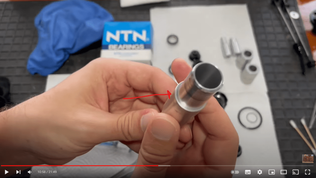
He then proceeds to rotate the spacer on the axle and the gap diminishes, the axle is a fixed point, and therefore any deformation must be in the spacer. As he rotates it, the deformation on the spacer is obvious. Bearing clearances are measured in hundredths of a millimetre and a gap that is visible is considered to be of the order of 0.1-0.2mm. To give some context, a human hair is around 0.075mm in diameter, a bearing clearance in small bearings is often 0.010mm ie 7x smaller.
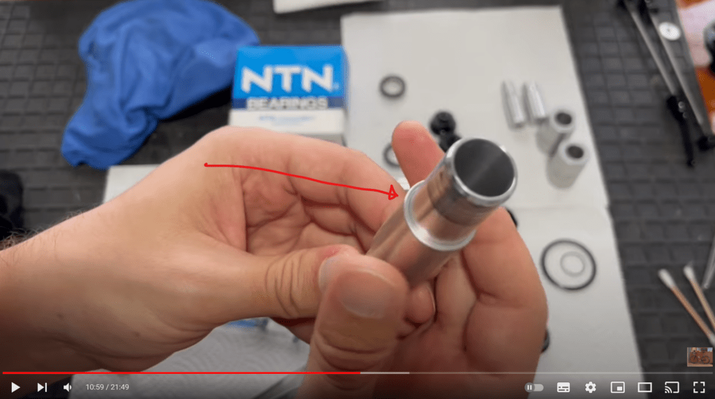
He then proceeds to turn the spacer around and repeat the process, note the spacer presents uniformly around the axle. This shows that this side of the spacer is comparatively round, i.e. the TIR is zero or very small.
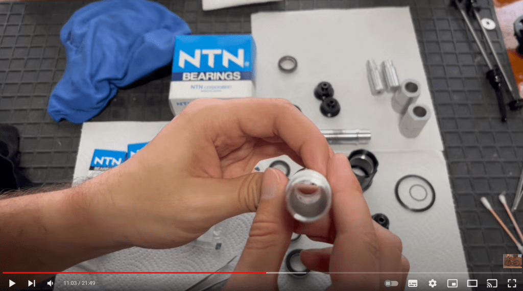
By the end of the video, Reginald had taken his wheels apart 3 times to check for faults and concluded the rocking motion was due to axle wear, he claimed an anodized axle would have alleviated this. Bearing Steel (A295 52100) has a hardness of approximately 1000 HV, and The 7075 Aluminium Axle of the winspace hub is approximately 100HV. The bearing steel is around ten times harder than aluminium and 3 times harder than anodized aluminium (which is typically only 0.050mm thick). It is likely that the damaged axle is a result of under rotation or precession, i.e. a mismatch in speeds between the bearing inner race and the axle. By definition, if underrotation is eliminated, then axle wear cannot occur, a “hardened” (albeit still soft) axle is a solution to the symptom and not the underlying cause.
Whilst a damaged axle cannot be ruled out as a cause of Reginald’s problems, it is almost certain that using a damaged spacer will have compromised the preload on the wheelset with an accompanying increase in under rotation, which would result in lateral play. He also removed the bearings three times which would have resulted in brinnelled bearings, increased bearing clearance and a likely fractured bearing cage.
Reginald claims to own a bike shop in Brunei and has many “satisfied customers”. In previous videos, he was observed removing and replacing bearings on a new set of wheels before selling them on to an unsuspecting customer. He claims his methods of bearing removal cause “No damage whatsoever”.
Conclusion
The internet has a propensity to propagate misinformation, and this is no exception. The use of this type of bearing puller on a preload sleeve is not recommended – SKF, NTN, FAG and NSK do not recommend the use of a device in this application. At best, a wheel will exhibit poor stiffness. At worst, the reduced stiffness will reduce the critical speed and make the wheel vibrate and induce early onset speed wobble.



I always knew Reginald Scot was a lying twat.
So if a bearing puller isn’t the right tool for working on customers high end carbon wheels with alu bearing housing… What tool does an engineer and manufacturer see as the best solution for this job? Which solution will he bring to the shops for bike maintenance at his high end 10K carbon aero bomber?
You need to get the bearing out without damaging the spacer – the spacer is reused the bearing is not.
How do you use a raceway extraction puller on a bicycle wheel hub? There is no shaft in the middle and nothing to counterhold against….
The jacking surface can be the housing, it depends if the interference fit is on the ID or the OD. in the case of wheel hubs it’s the OD
So, how do you pull bearing from hubs? You’ve drew a recess on the left side, is that to fit the pull tool?
Are there any ebay cheap raceway pullers available for bicycle sized bearings. I dont think most consumers would want to buy an SKF TMMD 100.
The removal varies, on a lot of them you hit the centre sleeve (axle) so it pushes the bearing out from one side and the knock the other one out from the other end.
So you hit the inner race on one side to give a little push and then make space for an internal pull tool without damaging the spacer?
Once you’ve hit one bearing and removed it, there will be no obstruction on the remaining bearing.
Hi Hambini, could you please make a video with proper procedure how to remove (and install) bearings from wheel hubs (front and rear with spacer)? Thanks